GitHub
how to calculate girth gear root clearance Formulas for gear calculation What is the standard root clearence and backlash of . SPUR GEARS Worm Gears Agro Engineers Helical Gear
how to calculate girth gear root clearance Formulas for gear calculation What is the standard root clearence and backlash of . SPUR GEARS Worm Gears Agro Engineers Helical Gear
βy = tan − 1(dytanβ d) For the geometry of a helical gear, the helix angle varies as a function of radius. This is observed in a helical gear tooth since the involute profile spans over a range of diameters. This results in the helix angle at the base diameter being less than at the tip diameter.
What is backlash clearance? Backlash, sometimes called lash or play, is clearance between mating components, sometimes described as the amount of lost motion due to clearance or slackness when movement is reversed and contact is reestablished. For example, in a pair of gears, backlash is the amount of clearance between mated gear teeth.
® Ring Gear • Installation Manual (Page 17 of 31) are tangent or operating apart. If scribe lines overlap, as in case NOTE: In some cases ( when the drive components are 3, it is necessary to separate the gear and pinion to provide aligned), it may be easier to move the shell as opposed to the necessary backlash. pinion pillow blocks.
During finish milling process of the spiral bevel gear (X40 steel) with a ballend mill cutter (HSLB2030), the parameter that has most influence on F was spindle speed ( %).
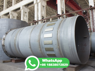
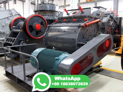
These ball mills are relatively small, bearing mounted on a steel frame. All ball mills are sold with motor, gears, steel liners and optional grinding media charge/load. Ball Mills or Rod Mills in a complete range of sizes up to 10′ diameter x 20′ long, offer features of operation and convertibility to meet your exact needs. They may be ...

Gear ratio is found by dividing the number of teeth in the gear being driven by the number of teeth in the driving gear. In this example, if Gear A was driving the system, the gear ratio would be 4/7. If Gear B was driving the system, the gear ratio would be 7/4. Hopefully, this introduction to gears gave you a helpful foundation to better ...
Our gears with ratio 222/27 ahs a diameter of more than 5m. b) Take care of the profile machiining the root radius etc should not be damaged during hobbing the involute. I saw in an article the tip clearance should be between to of the module for our module of 27 it is between to
of girth gear, pinions and drives. Repair and refurbishment Our repair and refurbishment team provides handson gear service including: Temporary repairs of crack and wear on girth gear and pinion Ball mill flange runout machining. Inspection services Beside the visual inspection of girth gears we also apply: Radial and axial runout ...
By current stan dards, girth gears can be as large as 14 meters (46 feet) in diameter, meters (44 inches) face width, and 50 module (.5 DP) tooth size, and weighing upwards of 120 tons. Flange mounted gears rely, in large part, on the mill structure to pro vide the stiffness and geometric stability required for successful operation.
NOTE 1 : The subscripts 1 and 2 of z 1 and z 2 denote pinion and gear. All calculated values in Table are based upon given module m and number of teeth (z 1 and z 2).If instead, the modulem, center distance a and speed ratio i are given, then the number of teeth, z 1 and z 2, would be calculated using theformulas as shown in Table . Table The Calculations for Number of Teeth
As a rule of thumb the average backlash is defined as divided by the diametral pitch; the minimum being divided by the diametral pitch and the maximum divided by the diametral pitch. [3] In metric, you can just multiply the values with the module: In a gear train, backlash is cumulative.
If the teeth are not machined by tooth cutters, and the teeth profiles are still kept intact, then the 2 gears will get jammed in formula for calculating the minimum teeth number without undercutting is:z min =2ha*/sin 2 αWhen ha*=1, and α=20°,we will have the z min =2*1/(sin20°) 2 ==17(always round down). So, the minimum teeth number for standard gears is 17.
I n order to determine the tooth size of a gear after taking into account the backlash allowance, you first must determine what the nominal tooth thickness should be. There are three methods for determining this value: chordal tooth thickness measurement, span measurement, and overpin or ball measurement. For this article, we will discuss measurement over rollers, which is more commonly known ...
Pinion Installation. Set up sub soles and sole as above for pinion mount. Place the pinion. Using Feeler gauges check to ensure a root gap of 6MM both ends move pinion into position as close as possible. Blue the Teeth on girth gear and roll mill using the turfers and check the coverage of the bearing blue.
The axial backlash is the shrinkage (displacement) in the stated center distance when a pair of bevel gears is set so the meshed tooth flanks of the paired gears contact each other. Fig. Circumferential Backlash Normal Backlash and Radial Backlash Backlash Relationships
align Copy View presentation slides online. ... 1/12/22, 8:15 PM How to install and align the girth gear and pinion | prmdrive
of the feeler into the two gears, and then the backlash can be calculated by formula (1). The feeler gauge used in this paper is shown in Figure 2. The thickness of the plug in the feeler gauge is,,,,,,,,,,, and respectively. The meshingteeth side clearance can ...
Gu [7] established a sixdegreeoffreedom gear pair model considering dynamic backlash and analyzed the influence of gear backlash and bearing clearance on the steady responses of the gear system ...
In SECTION 10, we have discussed the standard tooth thickness s. In the meshing of a pair of gears, if the tooth thickness of pinion and gear were reduced by Δ s1 and Δ s2, they would generate a backlash of Δ s1 + Δ s2 in the direction of the pitchcircle. Let the magnitude of Δ s1, Δ s2 be
The pinion is a small gear with a matching tooth profile to the ring gear on the ball mill. From a bearing point of view, there are two bearings at the end of the shaft on the pinion and there are ...
#cementfactory #rootclearence#backlash#Module#formula #girth gear#formula for root clearance#formula for Backlash#formula for module#gear #gear terminology
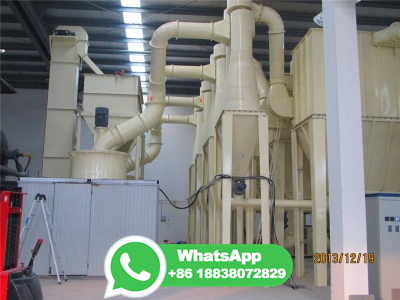
The DMG2 gear units cover the entire power range from 1,200 to 10,000 kW in standalone operation and up to 20,000 kW with the use of a dual drive. Worldwide, over 400 of these large gear units have already been deployed successfully. Your benefits at a glance. Compact and efficient drive. More effective use of the girth gear.
ity of cases to establish the root cause and define corrective actions to prevent a recurrence. This publication is intended to provide a basic understanding of bearing failures and failure analy sis. With the knowledge presented in this publication, it is possible to assess simple failure situations and start the right analysis.

Considering the microstructure of tooth surface and the dynamic characteristics of the vibration responses, a compound dynamic backlash model is employed for the gear transmission system. Based on the fractal theory and dynamic center distance, respectively, the dynamic backlash is presented, and the potential energy method is applied to compute the timevarying meshing stiffness, including ...
Backlash in gears is one of the nonlinear parameters that can act as internal excitation and highly influence the life of gear teeth. To investigate the influence of friction coefficient on the ...
Ball Mill Inspection Overview The following report provides a brief overview of the Ball mill inspection conducted on 18th February 2015 The gearing terminology is based on the AGMA 1010E95 standard, "Appearance of Gear Teeth" Pinion tooth measurements were recorded on both pinions. It should be noted that these measurements have low reproducibility and are for "general reference ...
CP (Circular Pitch) Circular Pitch (CP) denotes the reference pitch (p). For instance, you can produce gears at an exact integral value, such as CP5/CP10/CP15/CP20. Transformation from CP to Module m = CP / π CP10 is transformed to module as follows ; m = 10 / = DP (Diametral Pitch)
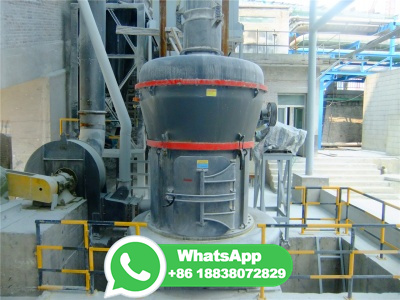
Gears and meshing Rotary kiln alignment Measurements ... · Meshing correct alignment of working teeth of pinion (or pinions) and girth gear. The root clearance and backlash parameter should be measured and recorded. Teeth contact can be observed by analyzing the contact pattern.
2. Adjustment of ball mill girth gear. According to the specification requirements: the radial runout of the large ring gear, the diameter of the pitch circle per meter should not exceed ; the end face of the large ring gear beats, the diameter of the pitch circle per meter should not exceed If it is out of tolerance, it needs to ...
For example, if we have a gear with a 1 DP, FHD tooth form, 150 in. center distance, and an anticipated 90F temperature rise above ambient, the required root clearance would be: Tooth Form Root Clearance Thermal Backlash Root Clearance Requirement: Proceed to Step .272 in. + .090 in. = .362 in. 638110 May 1999 Supersedes 1197
A gear center is the center of the pitch circle. Gear range. The gear range is difference between the highest and lowest gear ratios and may be expressed as a percentage (, 500%) or as a ratio (, 5:1). Heel Heel and toe. The heel of a tooth on a bevel gear or pinion is the portion of the tooth surface near its outer end.

Gear ratio and tooth numbers . Pressure angle (the angle of tool profile) α. Module m (With ANSI English units, enter tooth pitch p = π m) Unit addendum ha * Unit clearance c * Unit dedendum fillet r f * Face widths b 1, b 2. Unit worm gear correction x . Worm size can be specified using the: worm diameter factor q ; helix direction γ ...

© DZCrusher - كل الحقوق محفوظة